Reinforcement detailing is important in the construction engineering process. The step involves making complete drawings that represent the position, dimension, spacing, and quantity of steel reinforcement bars (rebars) in concrete structures. The construction teams review the steel against the drawings and instructions to ensure that the correct steel is placed. This helps maintain the strength, stability, and durability of the structure. In modern times, these different levels of precision and efficiency are done through computer-aided design (CAD) software.
Reinforcement detailing in CAD has done away with manual drafting. It has eliminated paperwork and increased reliability, accuracy, and trust between designers and builders. Within these advanced frameworks, steel placements can be accurately detailed, which means no unwanted delays due to ambiguity. The growing complexities of building structures increase the importance of CAD in reinforcement detailing.
Why Reinforcement Detailing Matters
The use of pure reinforced concrete aids in building large infrastructure facilities like bridges, dams, buildings, and most other structural purposes, stemming from the material’s strength and durability. What gives the material its strength is the integration of steel bars, as unbonded concrete is weak in tension.
Proper reinforcement strategies help ensure that a structure will function properly under a variety of loads. Errors in detailing can result in structural deficiencies, safety issues, and expensive repairs. CAD detailing reduces these risks through clear and accurate drawings corresponding to the construction requirements.
Benefits of CAD in Detailing Reinforcements
1. Accuracy
Every engineer and draftsman can achieve high levels of precision using CAD software. Bar placements are especially accurate due to snap tools, dimensioning, and layering. Achieving this accuracy with manual techniques is nearly impossible. Drawings such as plans, sections, elevations, or even detail callouts can all display rebars using CAD. Any changes made in one view are easy to propagate into all other views, thus reducing inconsistencies, which helps preserve design integrity.
2. Speed
The manual creation of reinforcement details is slow and monotonous. Many tasks, such as translating bar schedules into bending and even estimating quantities, are automated with CAD, enhancing work efficiency without diminishing the quality of the output.
Additionally, if there are any changes to the structural layout, CAD allows for the drawings to be updated within reason, avoiding the need to start over. This is especially useful for time-sensitive projects.
3. Templates and Standardization
The use of templates and practices is a standout feature for detailers using CAD. A large number of engineering firms have templates for standard structural components like beams, columns, slabs, and footings.
This boosts uniformity across multiple projects and helps to achieve compliance with the applicable regulations and standards. The use of templates also helps reduce the chances of overlooking critical details while enabling the creation and refinement of high-quality drafts under the guidance of a senior engineer.
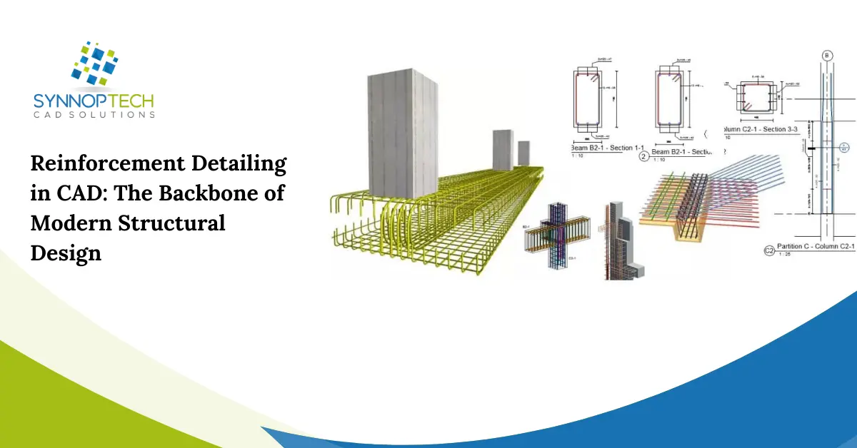
4. 3D Visualization
The latest CAD software, especially when augmented with Building Information Modeling (BIM), supports 3D modeling of the reinforcements. Such models enhance understanding of how the reinforcing bars are placed within the structure and their relationship with other utilities like electrical wiring and water pipes.
3D models of reinforcement aid in detecting possible disputes among various sections before actual construction starts. This enhances interdisciplinary collaboration while minimizing errors during actual construction work and delays associated with it.
Elements of Reinforcement Detailing in CAD
Reinforcement detailing consists of multiple components that should be incorporated in CAD drawings, including:
- Bar size and type: Designates the size and grade of each rebar.
- Spacing and placement: Specifies the distance between the bars and their precise position in the concrete.
- Bending shapes and lengths: Encompasses the bending details, hooks, and cut lengths of bars.
- Lap splices and anchorage: Displays the overlapping regions of the bars and the means by which they are anchored for strength.
- Bar schedules: A tabulated recapitulation of the total number, length, type, and shape of bending each bar.
For CAD drawings to be useful and practical on-site, all details must be presented accurately so there is no room for on-site discrepancies. CAD helps in incorporating these elements with precision and aids in organizing them systematically.
Popular Tools for Reinforcement Detailing CAD
Each tool has specific features that set it apart. A few of the most widely used include:
- AutoCAD: A household name in the industry for 2D reinforcement detailing. It allows full customization and integration with add-ons.
- Revit: Supports 3D modeling and is frequently used in BIM workflows. It supports reinforcement modeling and scheduling.
- Tekla Structures: Renowned for sophisticated detailing and fabrication-ready drawings. is widely applied to large infrastructure projects.
- AutoCAD Structural Detailing (ASD): Used by structural engineers, AutoCAD has a dedicated version known as ASD.
These features aid in automation and minimization of repetitive tasks, therefore improving the detailing accuracy and output in preparation for fabrication and construction processes.
An examination of the challenges and remedial strategies reveals the following:
Just like any other skill, this offers flexibility, but accuracy is a vital requirement. Some challenges include:
- Adhering to the local legislative building codes and regulations.
- Avoidance of reinforcement in intricate structural features.
- Integration with architectural drawings plus MEP: Mechanical, Electrical, and Plumbing.
Implementing all CAD best practices covered can mitigate the concerns outlined above:
- Check the capture and recorded measurements, check the placement of bars, and check recess dimensions if applicable.
- Employ CAD layer management to keep different types of reinforcement separate.
- Documenting information cleanly using consistent templates and controlled vocabulary naming schemes enhances usability.
- Revisions and updates to templates and code compliance ensure up-to-date libraries meeting legislative requirements.
All in all, CAD improves processes in place for reinforcement detailing.
The role of detailing reinforcements is significant in structural design. CAD provides automation in designing, which enhances precision and trustworthiness during the entire design phase.
For a skyscraper, residential complex, or even a bridge, CAD-based reinforcement detailing is a useful and intelligent choice that sustains long-term structural integrity.